I purchased the BrickBling Light Kit for my LEGO Enterprise-D but was disappointed to see from the instructions that much of the wiring was visible externally, and the light bars for the warp nacelles were stickers stuck to the outside. The result was that while it may look nice in the dark, the appearance otherwise was not what I was hoping for.
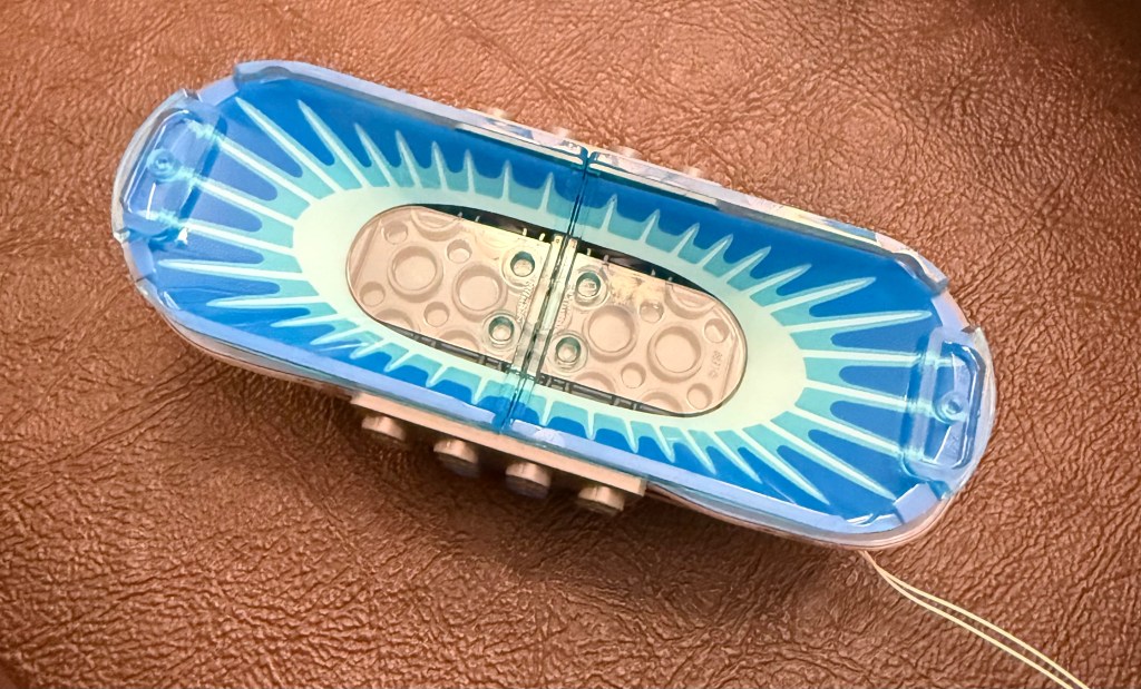
My goal was to adapt the light kit so that the model maintained it’s normal appearance, hid the wiring, and was illuminated from within as much as possible.
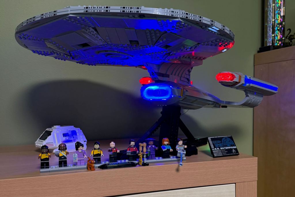
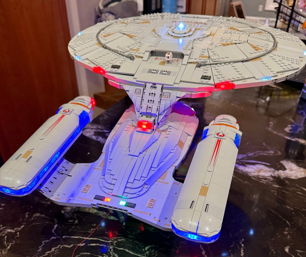
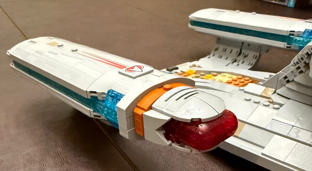
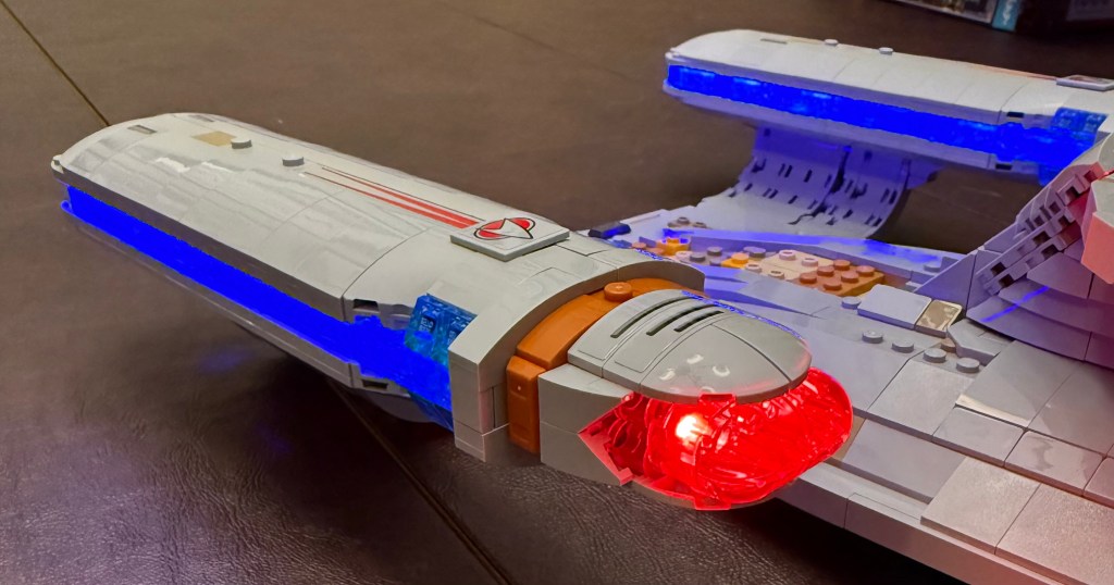
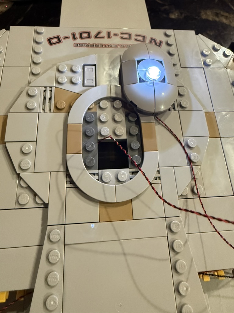
Here is the result.
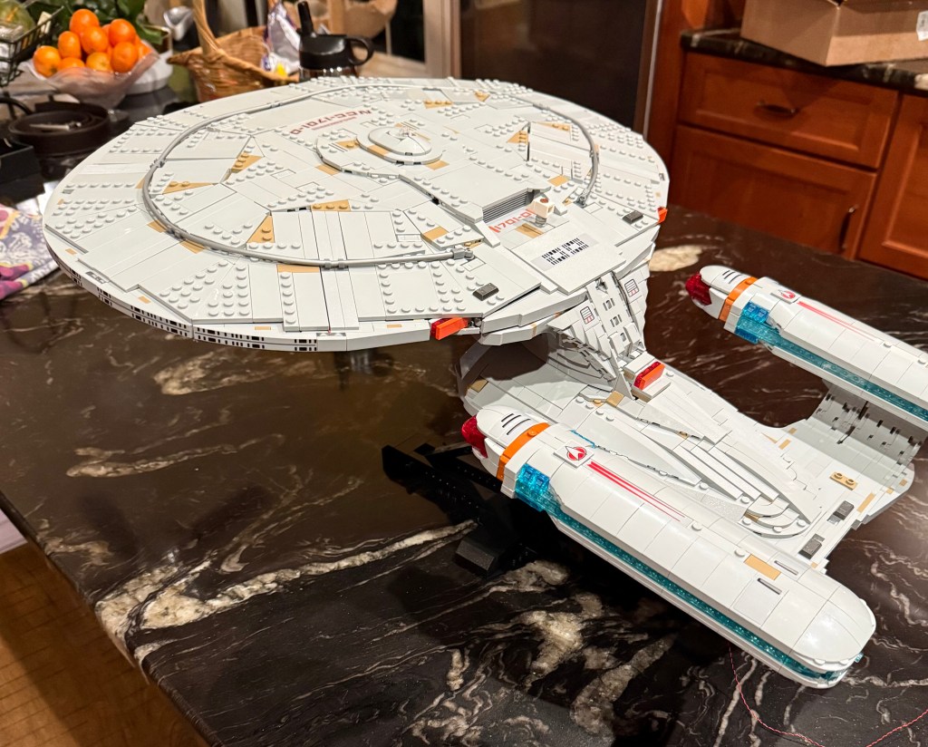
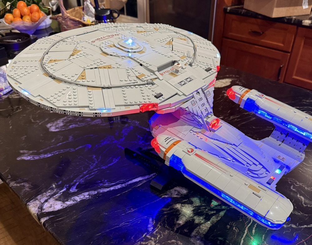
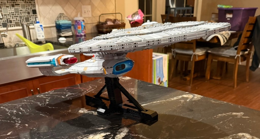
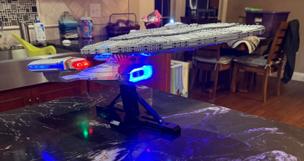
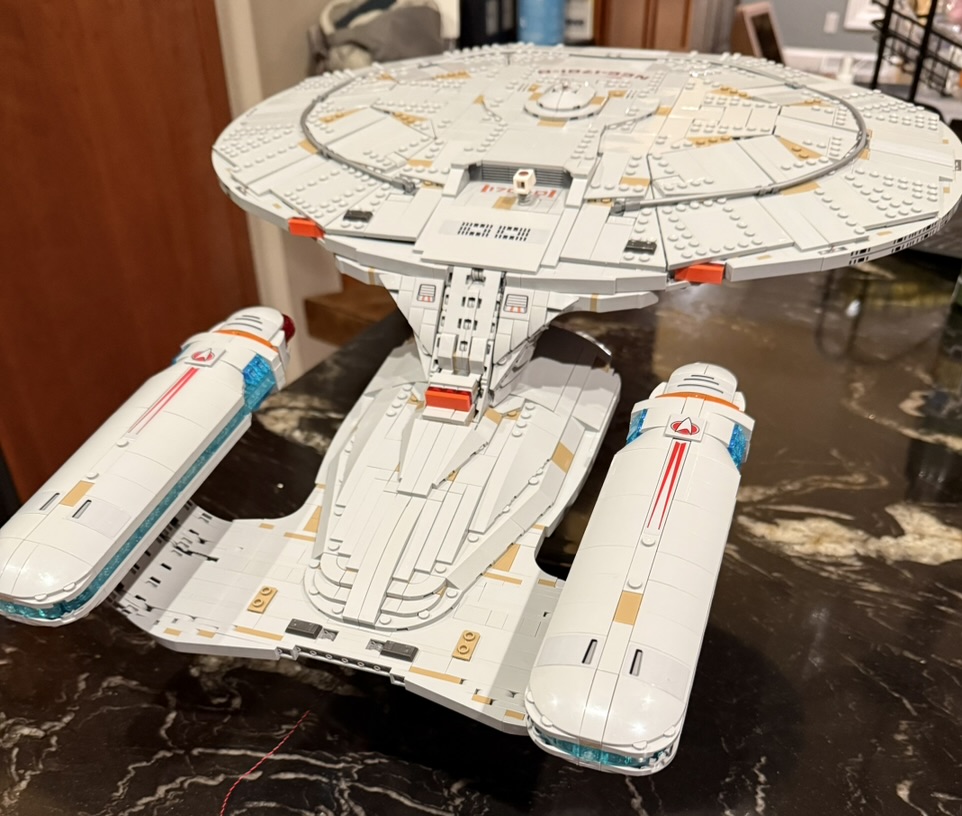
This was accomplished through the following:
- Reorganizing the wiring layout
- Minor restructuring of interior spaces of the LEGO kit
- A complete reworking of the inside of the warp nacelles and supports using replacement LEGO pick-a-brick parts
I’m going to go through the modifications I made in the order that they appear in the original build instructions, but first I want to give the list of parts I ordered for the nacelle rework and provide the overall wiring plan.
Lego Order
| Item | Decription | Quantity | Purpose |
| 4211535 | Technic Brick 1×1 (Medium Stone Grey) | 24 | Hide power cable to warp nacelles |
| 6450820 | Plate 1×3, Rounded, No 1 (White) | 8 | Interior of warp nacelles |
| 6514223 | Flat Tile 1×2 (Transparent) | 8 | Interior of warp nacelles |
| 6514001 | Plate 1×2 (Transparent) | 14 | Interior of warp nacelles |
| 6248890 | Plate 1×2, Rounded, No 1 (Medium Stone Grey) | 4 | Hide power cable to warp nacelles |
| 6513964 | Plate 1×1 (Transparent Light Blue) | 24 | Interior of warp nacelles |
| 6514455 * | Brick 1x2x2, with 8 Knobs (Transparent) | 24 | Interior of warp nacelles |
| 6130008 * | Cross Axle 5M | 2 | Interior of warp nacelle |
| 6514007 * | Plate 1×2 (Transparent Light Blue) | 46 | Interior of warp nacelle |
| 4211395 | Plate 2×4 (Medium Stone Grey) | 4 | Underside of secondary hull |
| 4211425 | Plate 1×8 (Medium Stone Grey) | 1 | Channel on secondary hull |
| 4210998 | Plate 1×8 (Dark Stone Gray) | 1 | Channel on secondary hull |
| 4211445 | Plate 1×4 (Medium Stone Grey) | 2 | Channel inside secondary hull; Rear navigation lights |
| 4211398 | Plate 1×2 (Medium Stone Grey) | 2 | Rear navigation lights |
| 4514846 | Plate 1×12 (Medium Stone Grey) | 1 | Rear navigation lights |
| 4211481 | Flat Tile 1×8 (Medium Stone Grey) | 1 | Channel for defector dish lighting |
| 4211428 | Brick 1×3 (Medium Stone Grey) | 2 | Shuttle Bay |
These can be ordered from https://www.lego.com/en-us/pick-and-build/pick-a-brick
The parts on the list marked with * were special orders so took several weeks to arrive in a separate delivery from LEGO.
Wiring Plan
The BrickBling lights, cables, and connectors come in a set of numbered bags which are referenced in the diagram.
Secondary Hull
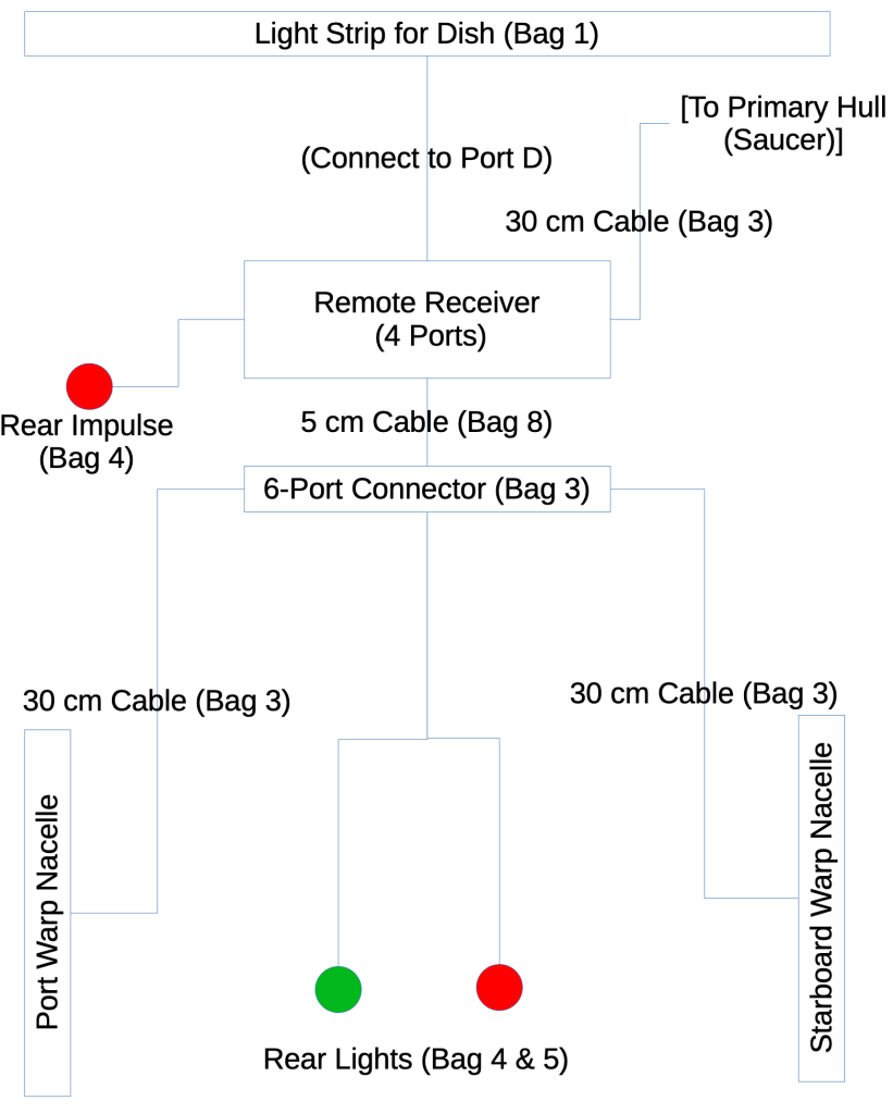
Power comes in from a USB cable connected to the Remote Receiver on the underside of the hull. I didn’t show that on the diagram. There’s a lot being connected up here, so lights are attached both directly to the ports on the receiver, and one of those ports is connected to another 6-port expansion strip.
Warp Nacelles
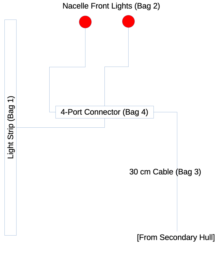
Unlike the original instructions where there are two light strips and a 6-port connector all stuck to the outside of the nacelle, I used a 4-port connector and a single light strip inside. The whole interior structure of the nacelle is transparent to support this.
Primary Hull
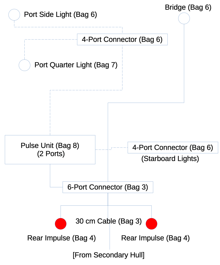
The remaining 6-port connector is used in the primary hull to route power from the cable coming from the secondary hull. This powers the always-on bridge and impulse drive lights, and also connects to the light pulse controller that then routes to the four blinking lights on the outside of the saucer via the remaining two 4-port connectors.
In the end you use all the provided parts from the lighting kit except you have two light strips from bag #1 left over.
Nacelle Supports
The challenge with the nacelle supports is that they are only one brick layer thick, so there’s no easy place to hide the wiring unless you go inside. For this I used a total of 24 Technic 1×1 bricks in medium stone grey to create a tunnel from the midpoint of the hull to the nacelles.
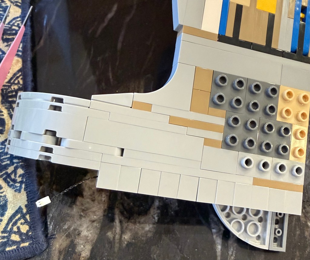
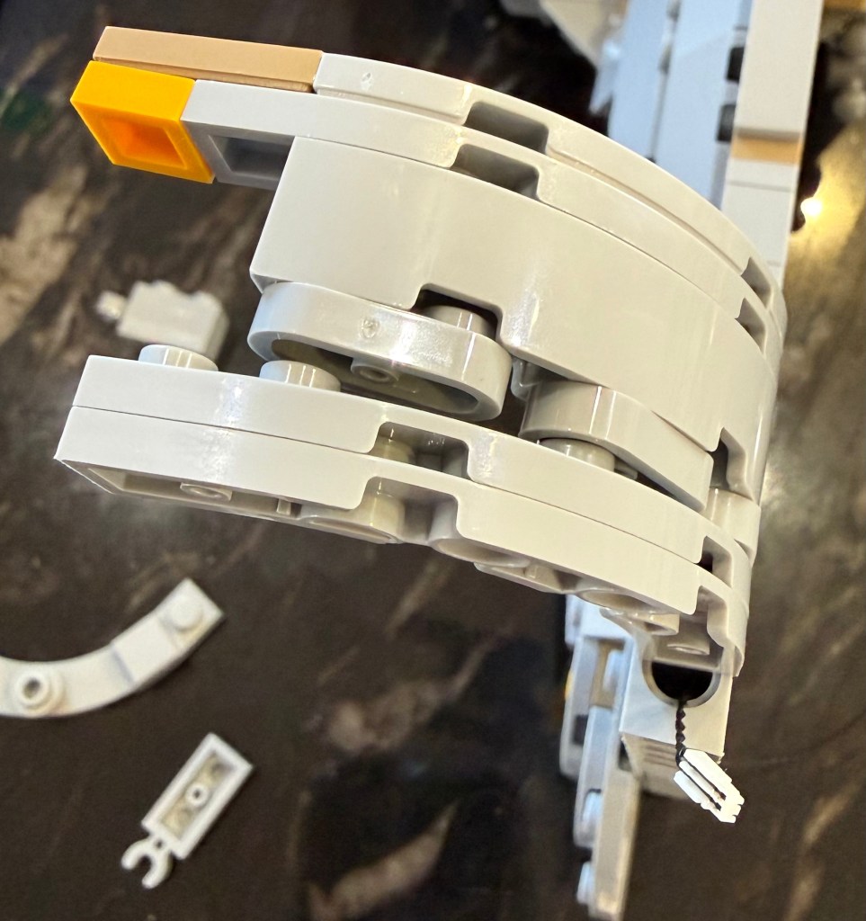
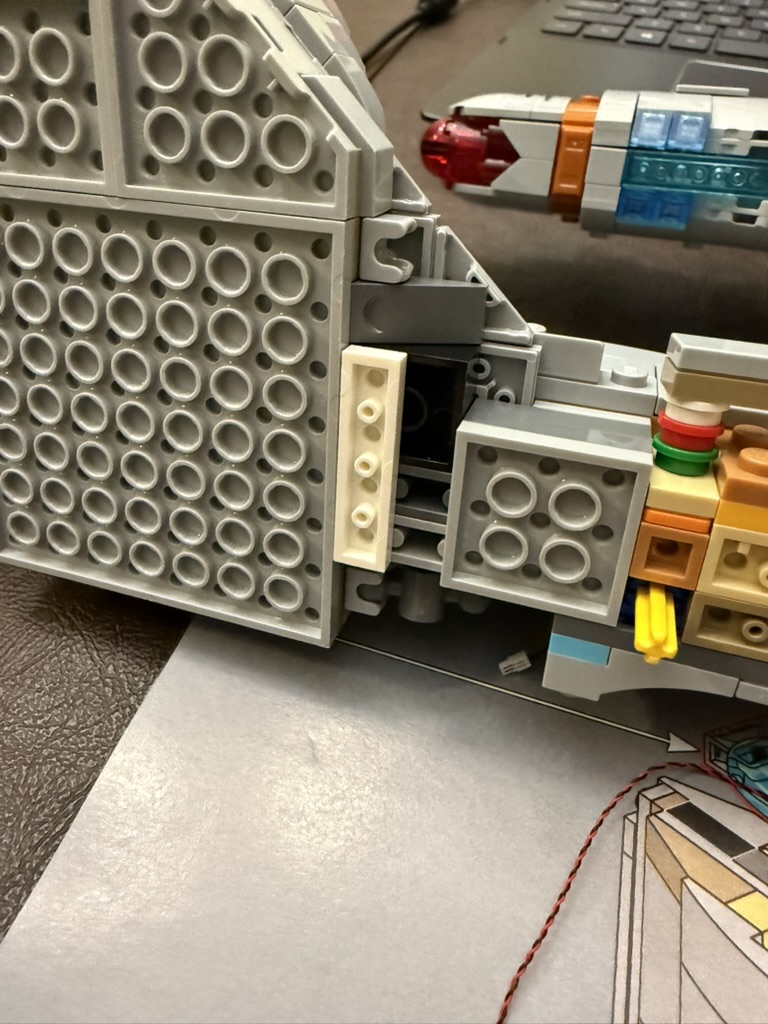
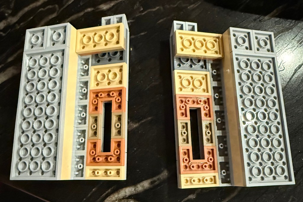
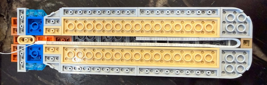
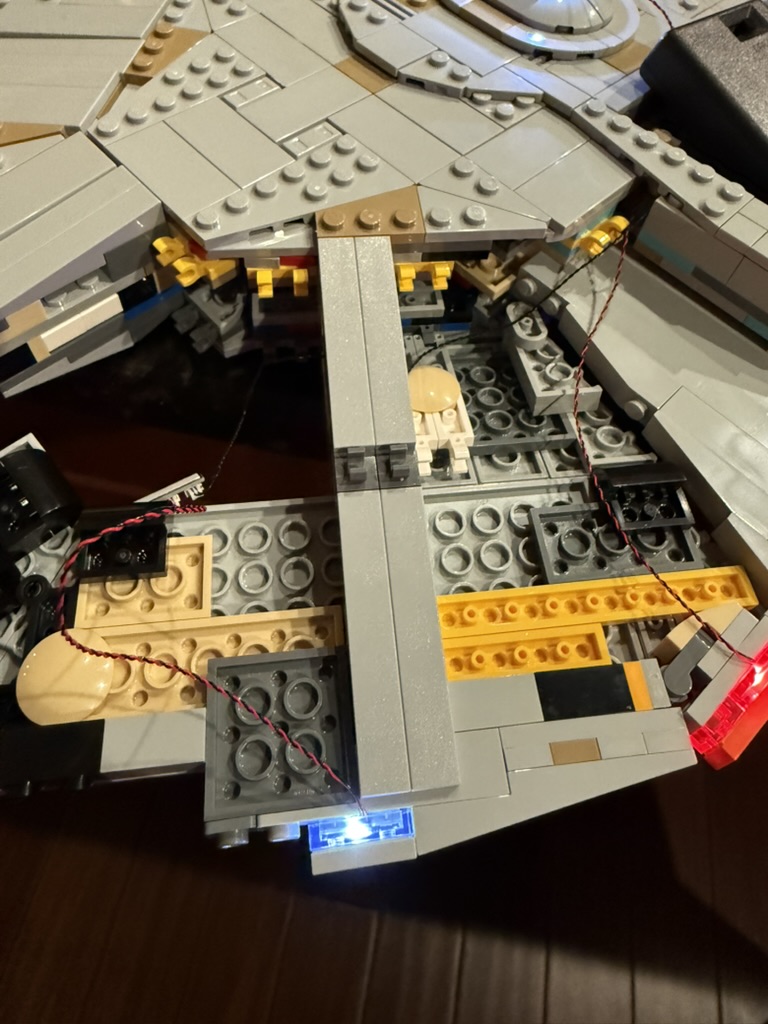
Before continuing past step 93 (page 65) you want to restructure the supports to allow you to thread the power cables inside to the warp nacelles.
As you can see above, I replaced the row 4 from the end with a series of 11 of the Technic bricks. This required moving the row with the posts to hold the two sides together down one row.
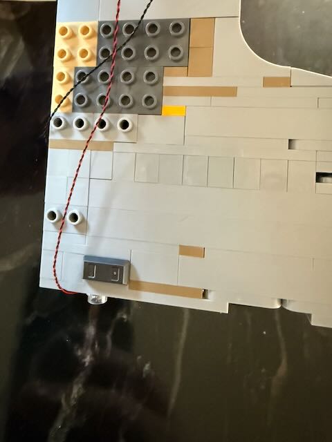
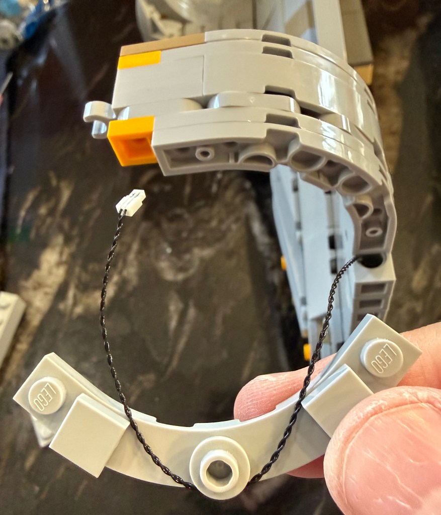
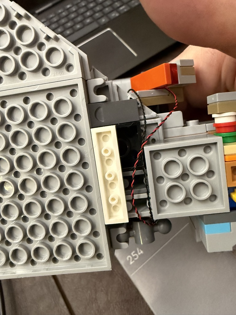
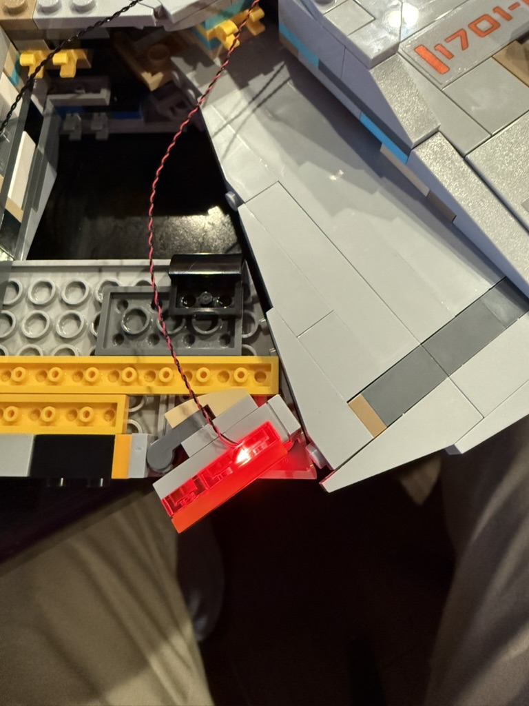
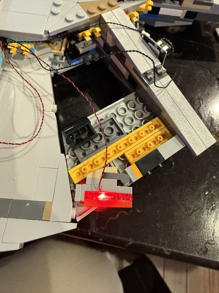
Here is a view while I was in the process of rebuilding the supports. You can see that I threaded one of the 30cm wires from bag #3 through the channel I created.
Here is another view of the wire coming through before being threaded up to the nacelle. There’s no easy way to hide the wire in the curve of the support, so you just tuck them in as best you can. This is one of the more exposed parts of the wiring, but very minor compared to the original wiring design.
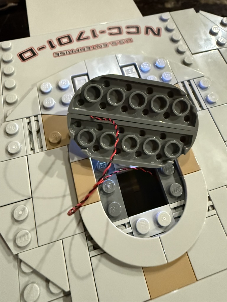
The pieces along the curve get replaced by a round piece in the middle and two square ones. I think those were spares from earlier in the build process. The wire just gets weaved back and forth through them to keep it aligned to the shape of the curve.
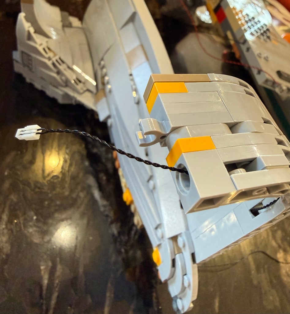
A final Technic part is placed at the top and the wire exits from there into the warp nacelle once it’s attached.
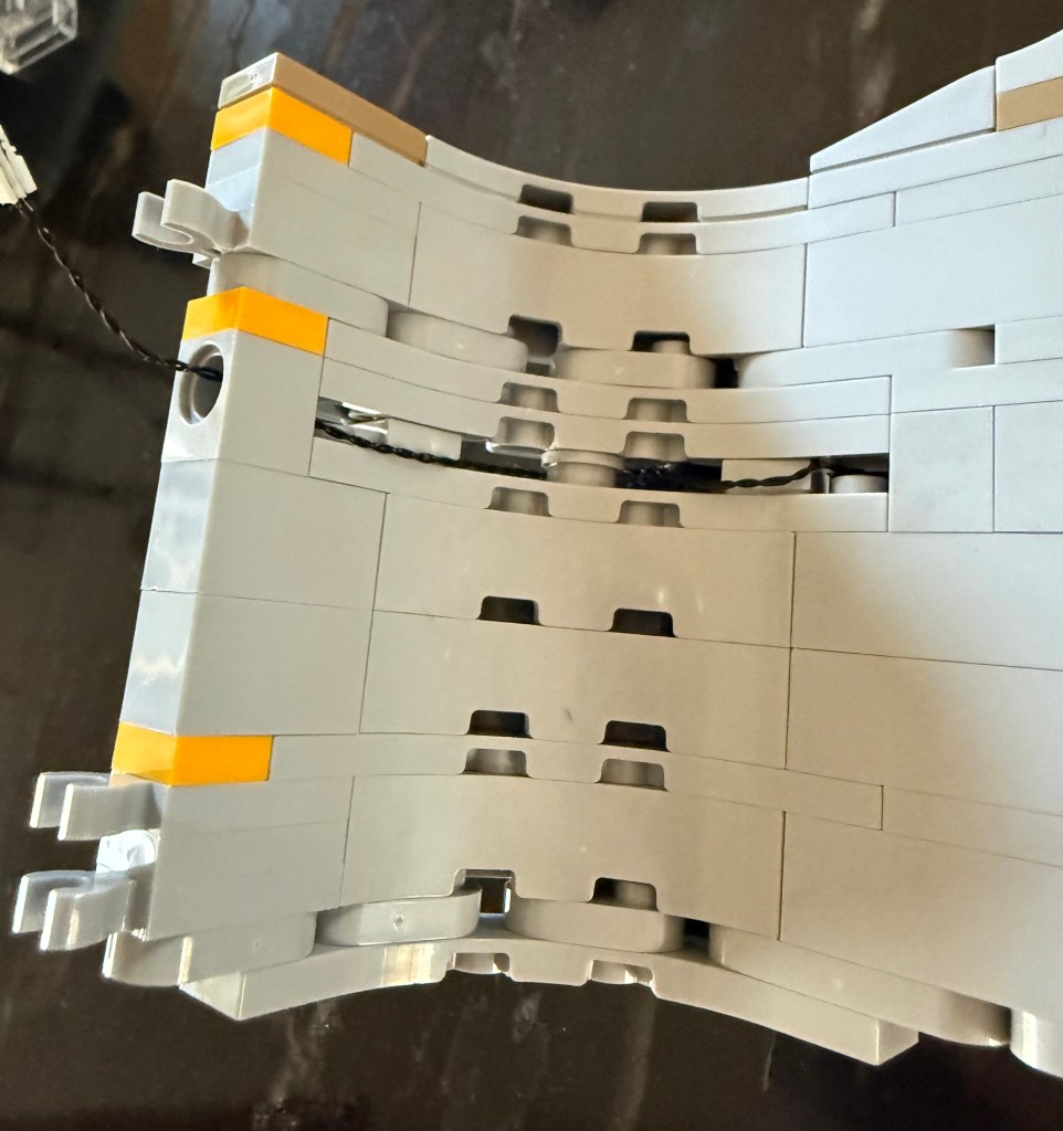
The overall location of the connectors at the top of the support have been moved as well. Note that there is only one in the front now. They had to be relocated to support all the changes to the interior of the warp nacelles.
Wiring Channels
Step 203 (page 124) shows the starboard side of the hull before being joined to the port side in the following step.
You want to replace the 2×4 piece with a single 1×4 to create a channel for the wiring to run from the underside of the hull to the impulse engine and primary hull. You may want to go ahead and run that 15cm red light from bag #4 and the 30cm cable from bag #3 before putting the two sides together.
When putting the two sides together, have the wires to the nacelles come out to the underside of the hull.
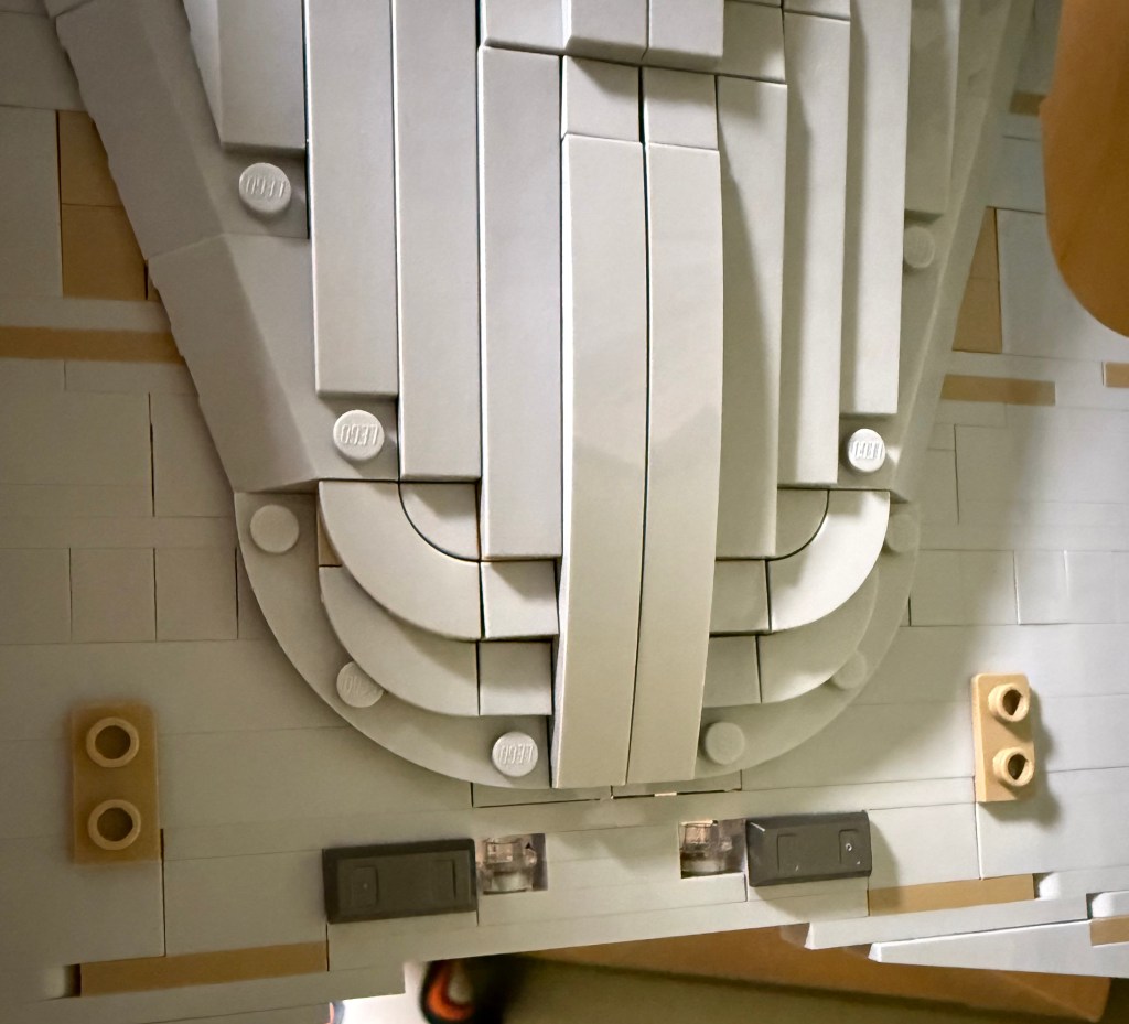
Speaking of the underside of the hull, you want to replace the large 2×8 flat piece by the opening for the display stand with a single 1×8 flat piece to provide a channel for the wiring from the defector dish light strip.
Starting in Step 215 (page 130), you want to modify that part of the underside of the hull to also create a channel for the wiring.
You’re going to replace the 4×8 flat piece from step 216 (page 130) with a couple of pieces to create an opening for the wires to pass through. You may want to wait until you also wire up the rear navigation lights before you replace the flat tiles to rebuild the exterior.
Room for Parts
The original lighting instructions have you placing the remote control board and a port connector in the underside of the hull. Impossible, as far as I can tell.
Those two hull pieces you build in steps 231 (page 135) and steps 244 (page 141) need to be modified.
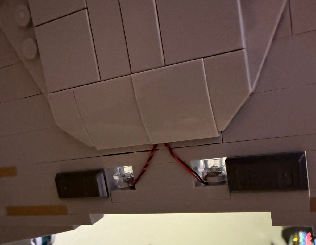
You need to remove the 2×4 red brick and 2×8 piece below it and replace them with 2 2×4 pieces (I have a 2×4 and 2 2×2 in the photo). You need to match the color for the ones on the outside.
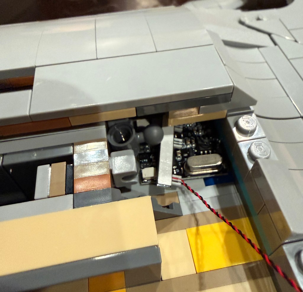
This will give you plenty of room for the wiring and control boards. As in the original lighting instructions (step #84), run the USB power cable out between these two sections, close to where the display stand connects. But you have to get the deflector dish and rear navigation lights wired up before you close everything up here.
Deflector Dish
You want to place the light strip from bag #1 for the dish at step 252 (page 147). See step #38 in the light kit’s instructions as well.
You want the light strip the match the outside border of the dish pieces as closely as possible. Too far in and you can see the line through the pieces. Too far out and you can see it around it. I had to take the two dish pieces off several times to make adjustments to get it just right.
After attaching the dish, you can then run the wire to the connectors under the 1×8 flat tile you replaced earlier.
Impulse Engine
Step 263 (page 159) is where you assemble the impulse engine on the secondary hull. Use the light you threaded through earlier and build as per the lighting instructions (step #109).
Rear Navigation Lights
The instructions for the lighting kit have you place these lights at the end of the hull. The cables do not appear to be long enough to actually pull this off.
Looking at footage for the Enterprise-D, these lights are not at the end of the hull, but somewhat inset, on the top and bottom of the hull. So I did some improvising and embedded them in the hull.
The two halves of the hull do not hold together as well as I would like, causing a slight sag, so at the end of the hull (before placing the pieces from step 264 (page 160), I pulled what was there and placed a long 1×12 piece between them and then used 2 1×2 and a 1×4 pieces along with the lights from the lighting kit (bags #4 and #5) to embed the lights in the hull. See lighting instructions starting at step #49 for the light set up.
Run the wiring along the underside of the hull and into that same channel you created for the wiring to the warp nacelles. This is one of the few areas with some exposed wiring, but it can’t be helped.
Now you can close up the underside of the hull.
Warp Nacelles
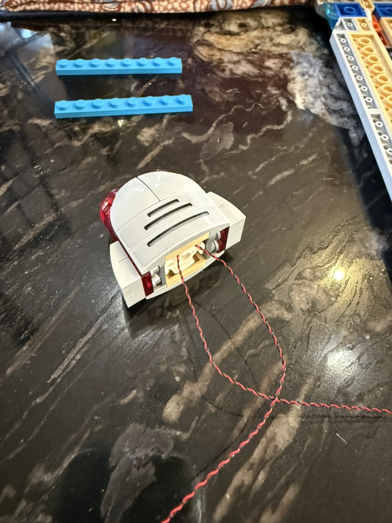
This is the most significant modification to the original design. My recommendation is to go ahead and build the nacelles all the way to step 404 (page 230) so that you understand the original structure of them before we rebuild the middle layer to make it entirely transparent.
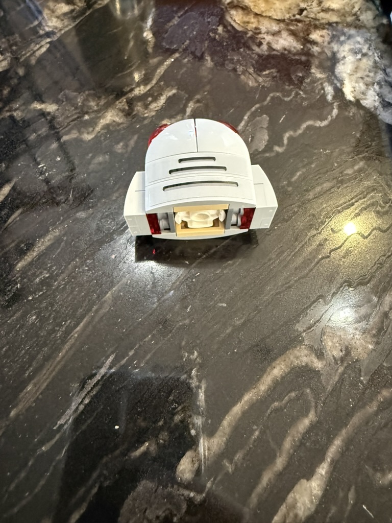
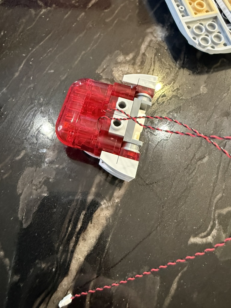
For the modifications, you first want to pull the top off the nacelle and then pull off the front. You can also set aside the small piece on the underside of the nacelle for now and just re-attach it when you connect the nacelle to the support.
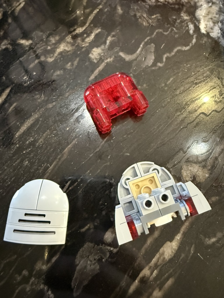
The trick to making the lights in the front look good is to make them point forward. The original instructions just have you slide the lights in (step #9), but that won’t get the look that you want.
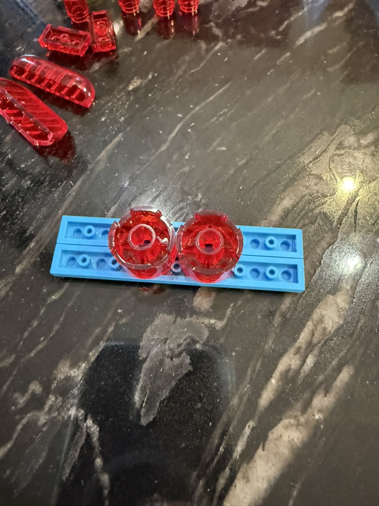
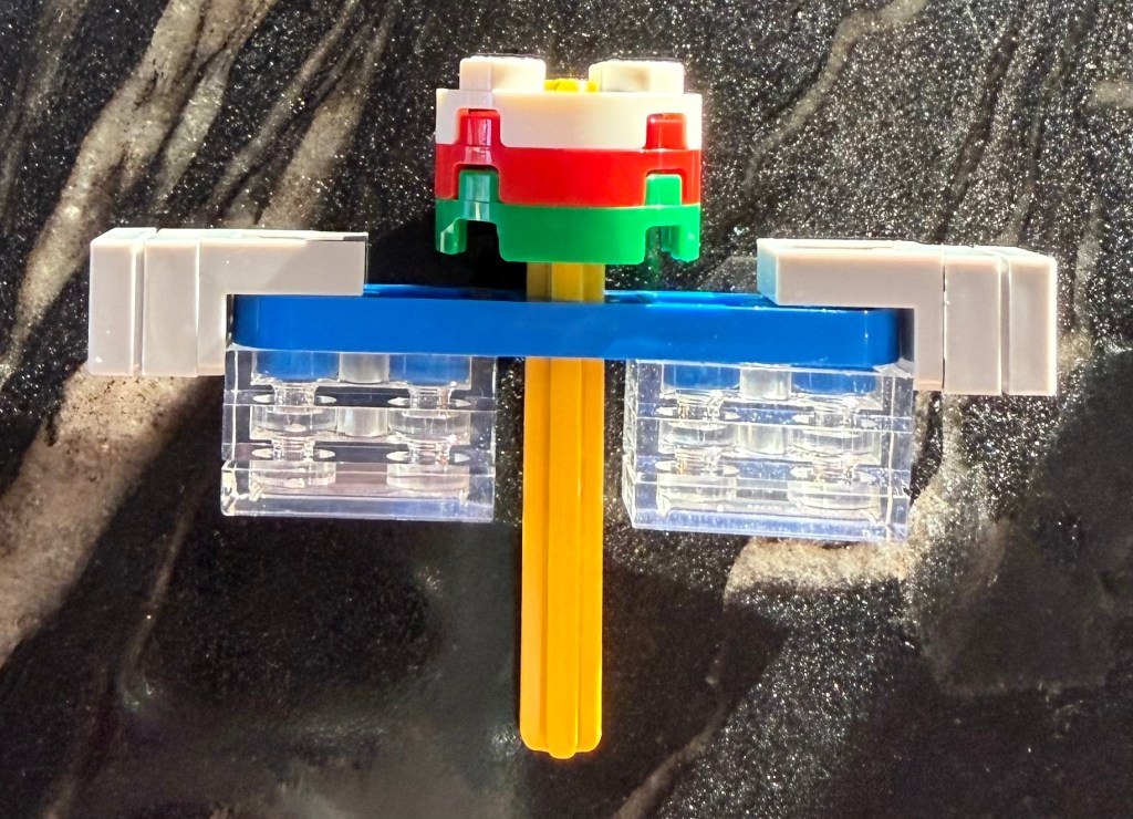
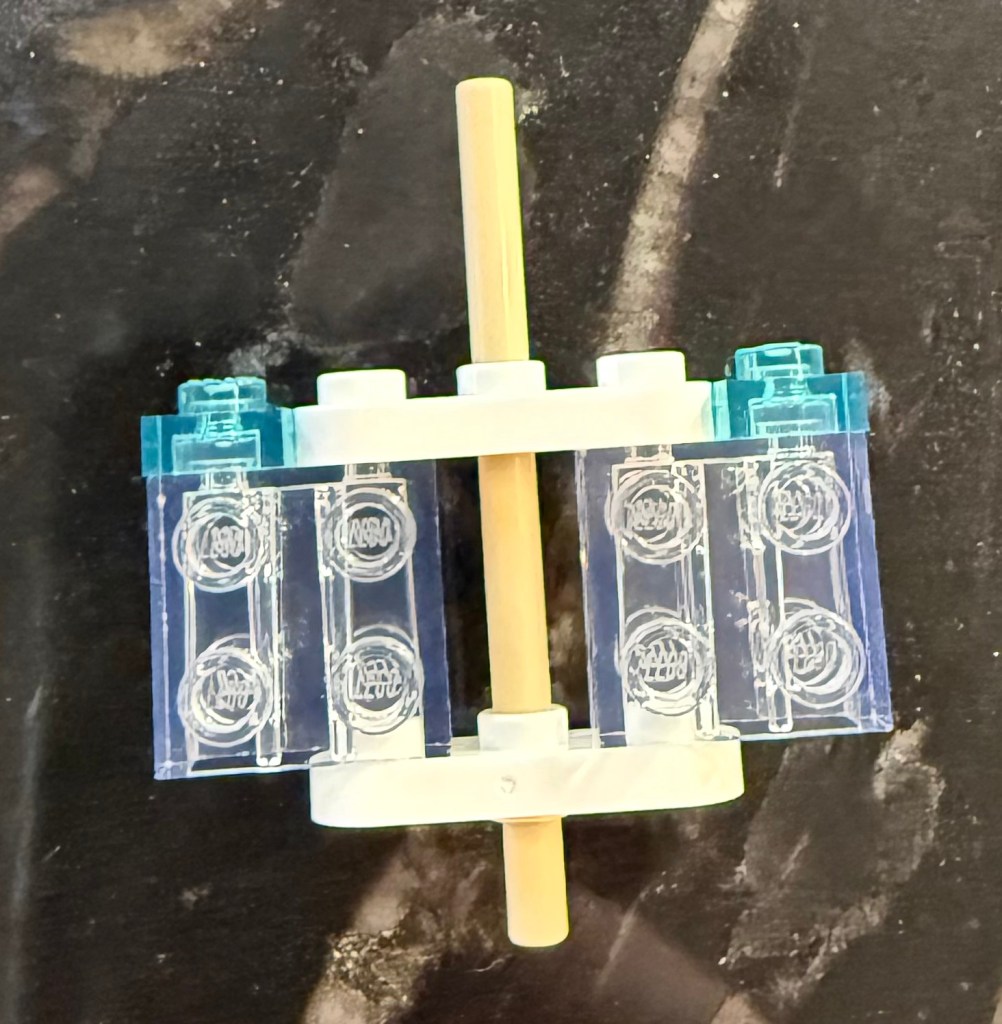
So you need to completely take that transparent section apart and reassemble it with the lights set properly. Start by placing the two round pieces face down on a temporary platform of two 1×8 flat pieces.
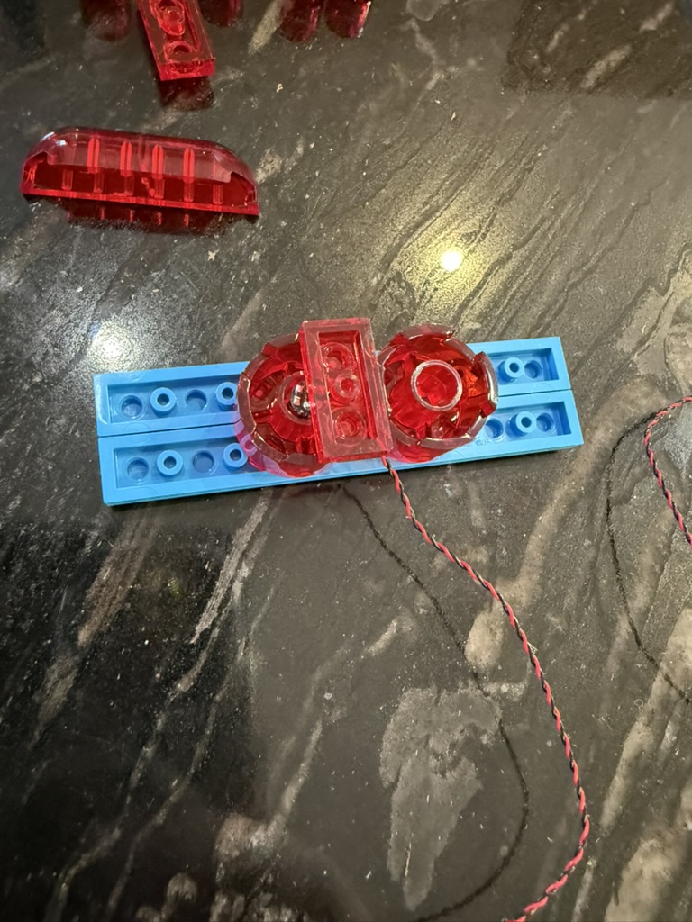
Position the light chip to face down in this orientation, with the wire coming in towards the middle. Use the 1×2 red piece to hold in in place. Do the same on the other side.
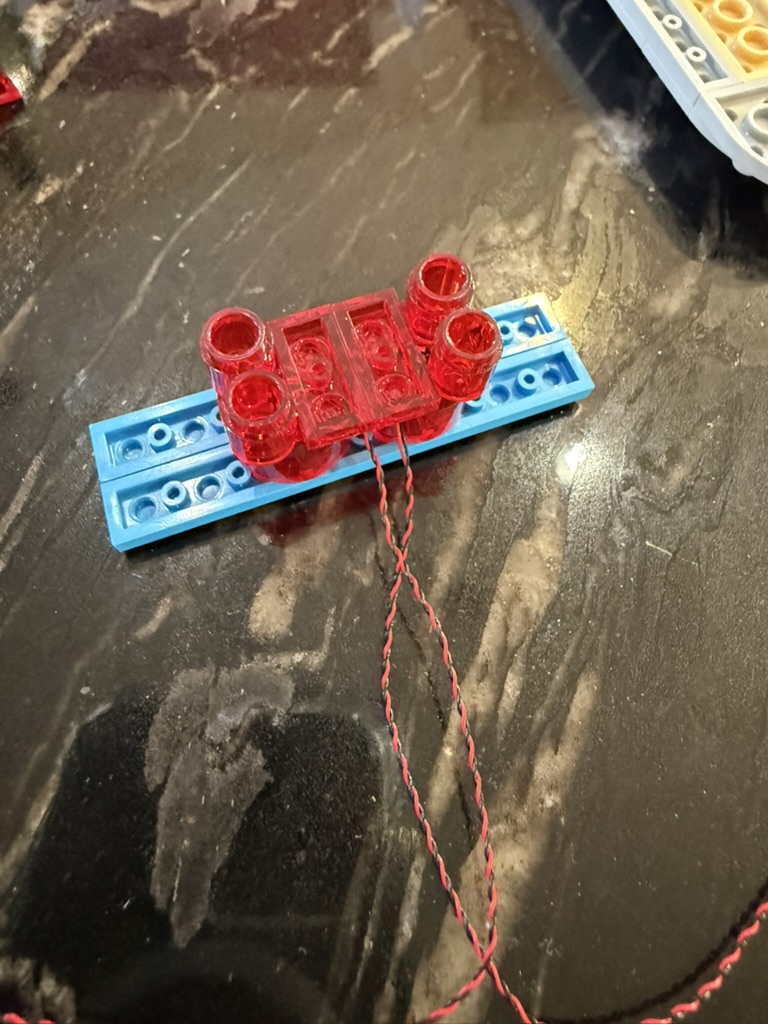
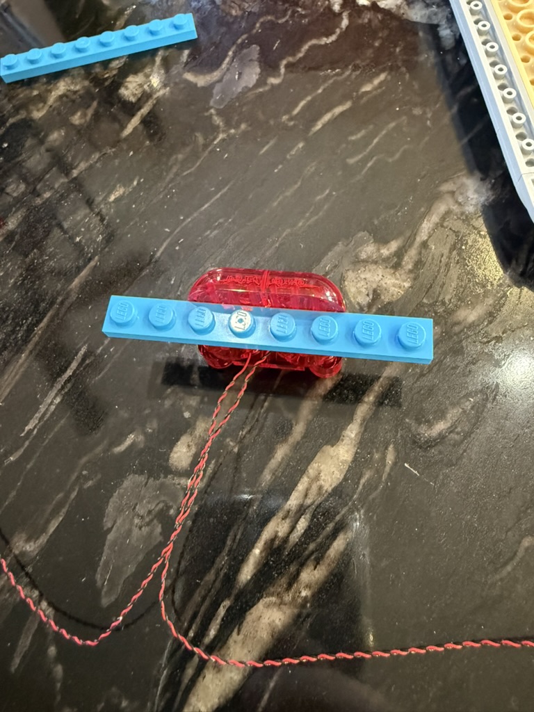
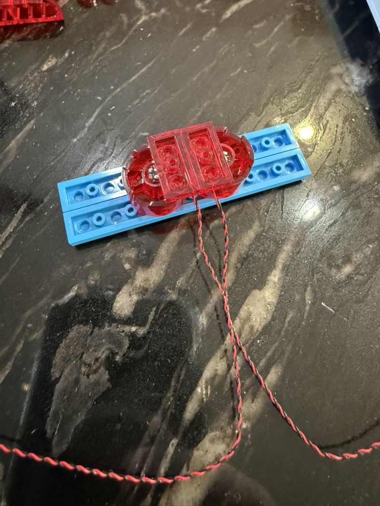
Place the round pieces back, and then flip it over and replace the 1×4 rounded front pieces one at a time to maintain stability.
Place the transparent lighting pieces back on the base, and then put the top panel on the completely rebuilt front, now with wires coming out the top middle.
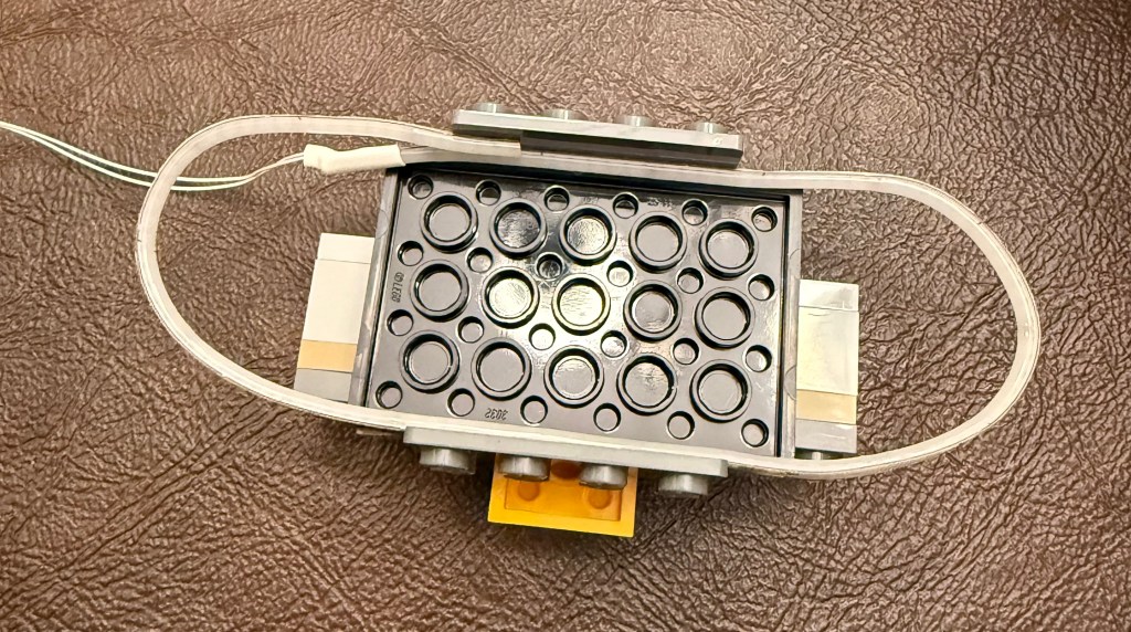
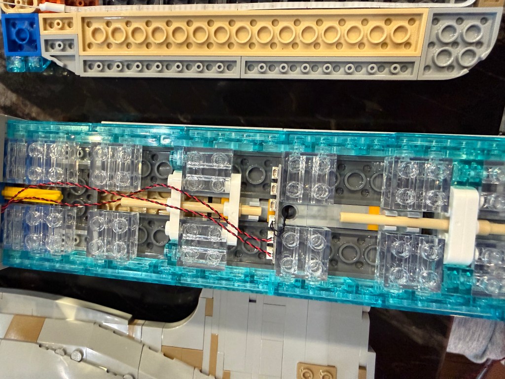
The next step is to remove the middle structure from the main part of the nacelle and start to build it back up with all transparent parts.
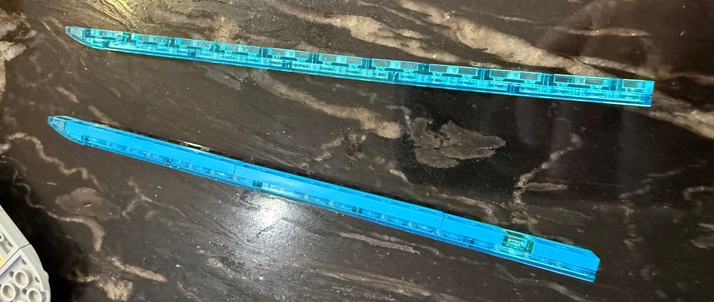
The first step is to remove the transparent blue side panels with the solid blue backing pieces and rebuild them using the matching transparent 1×2 pieces. (I wanted to use matching 1×8 pieces like in the original, but you can’t get transparent versions of those.)
Use the the new transparent pieces to build up a new end structure for the back of the nacelle.
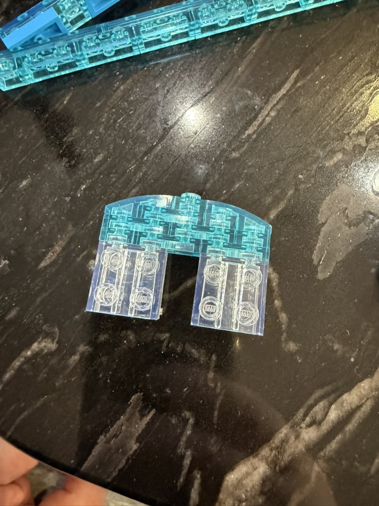
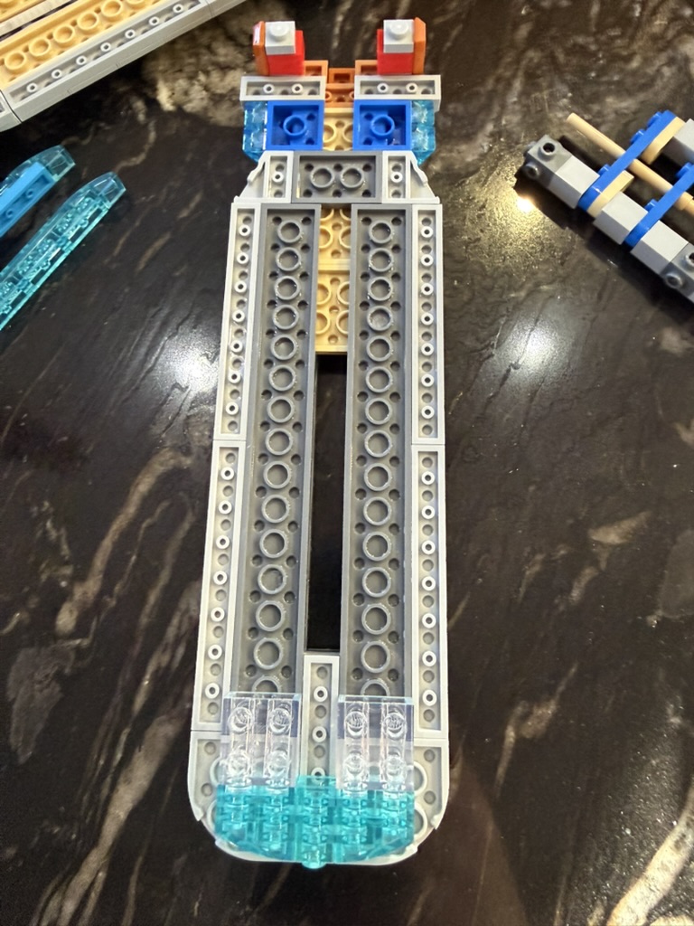
Rebuild the part that the front of the nacelle connects to and the new connection structure for connecting the nacelle to the support on the hull.
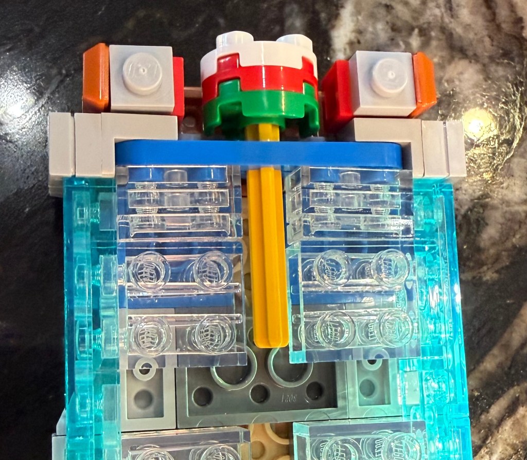
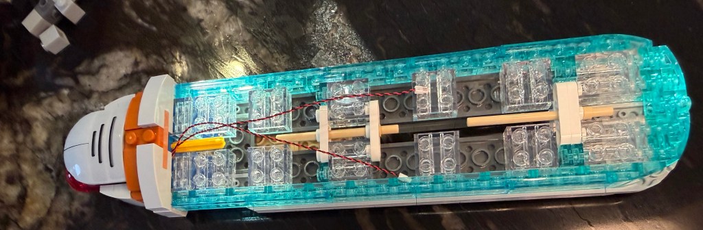
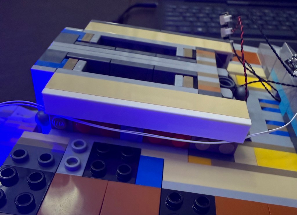
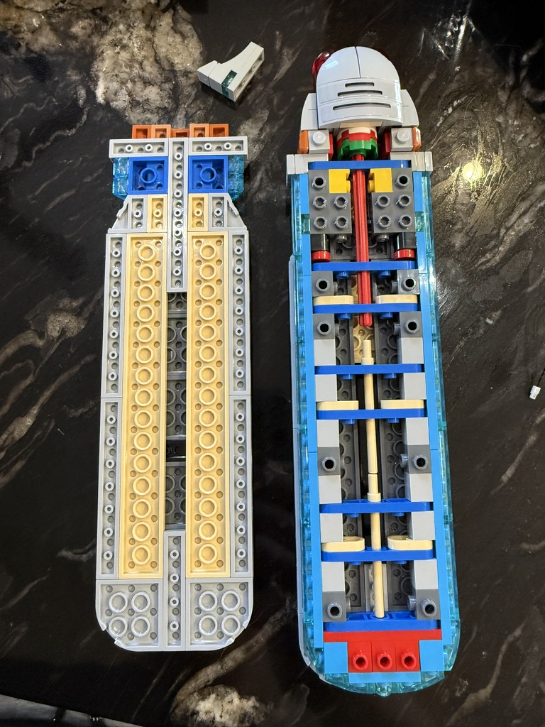
Here is the overall structure along with a couple of detail shots. Note the post in the rear is two rounded 1×3 stacked together for stability.
The longer 1×8 and 1×5 pieces in the top are replaced with 1×2 (internal) and 1×1 (external) pieces to lengthen the channel that the light strip can be placed in. Here I was able to reuse extra pieces from the set.
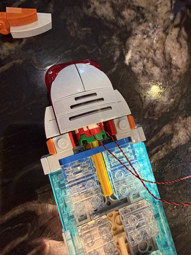
Attach the base to the hull support and use a 4-port connector to connect up the 2 front lights, light bar in the top, and the power feed coming up from the hull support (this photo shows a 6-port connector, which got changed out later for a 4-port).
Primary Hull
All the lighting and wiring in the primary hull are on the top and back half. The idea is to run the wiring from the secondary hull into the shuttle bay and routing from there.
In step 62 (page 39), instead of installing a 1×4 block, use a 1×3 block to create an opening to the rest of the hull. Also replace the yellow square with a round piece to allow the wiring to slip through. Here you want to get all the wiring in place for the pulse controller and the side lights. See the primary hull wiring diagram.
I recommend against attaching the primary hull to the secondary in step 106. We’ll do that at the end.
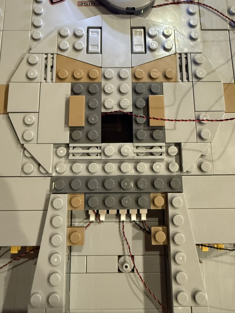
In step 157 (page 94), replace the large 4×12 plate with a set of plates to allow an opening under where the bridge will be placed. Thread the light for the bridge through that opening.
At step 163 (page 100), build the bridge separately from the rest of the hull and route the light wiring between the pieces. See lighting instructions #123 for details on the light itself. Then attach the bridge.
Starting at step 261 (page 146), hold off attaching the panels that fill in the rest of the back half of the hull. You need to run wiring in there first. Just set them aside in a way so you remember what goes where.
Starting at step 377 (page 191), build the impulse engine lights per step #104 of the lighting kit instructions.
At step 417 (page 212), install the pulsing quarter-lights per step #137 in the light kit instructions.
At step 418 (page 214), install the pulsing side lights per step #141 in the light kit instructions.
Now go back and install the hull panels you set aside. I found the best way was to separate them, install the smaller bottom panel first, adjust the wiring so everything is in place, then connect the top panel to the hull and bottom panel by lining them up carefully and pushing inward.
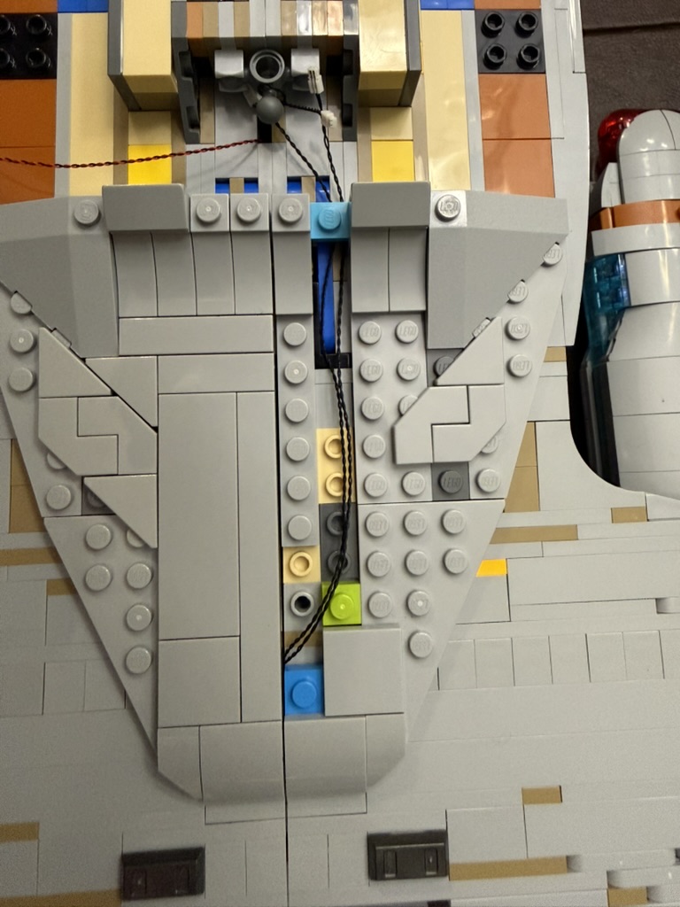
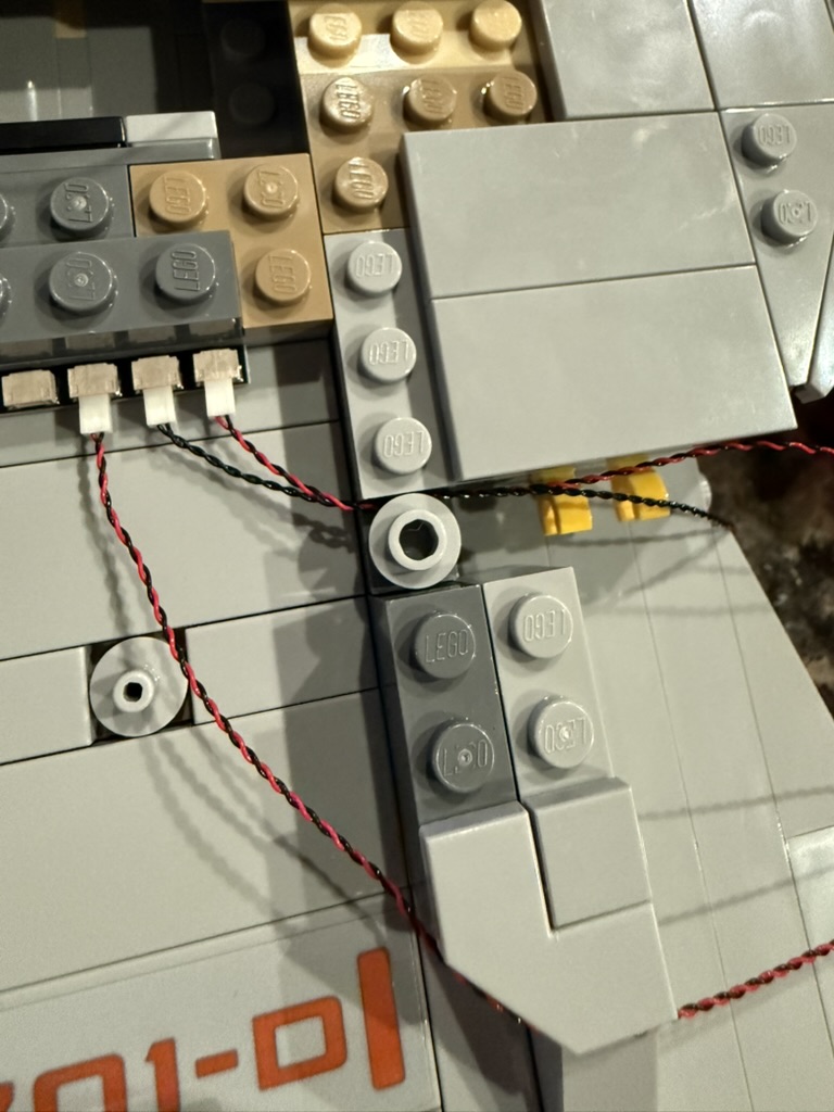
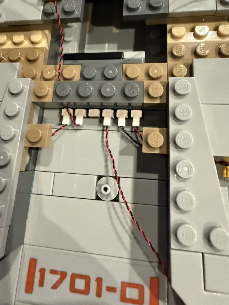
The final step is to attach the primary hull to the secondary and connect the wire to power the primary hull lights. To hide that wire, I ended up routing along between the neck and the starboard shuttle bay. I then removed the large panel behind the main shuttle bay and the one marked “1701-D” and ran the wire under that. So I’ve lost the ability to easily separate the saucer section, but at least the wires are hidden.
Enjoy!
